| The FOLDINGSS Research Spacecraft in a nutshell |
| Mass |
250 metric ton |
| Habitat Configuration |
3 spokes, 2 x 330m^3 envelopes ea |
| Inertial Gravity |
1/6G inner envelope, 1/3G outer |
| Habitat RPM @ InG |
4 RPM |
| Habitat Volume |
2150m^3 |
| Habitat Living Area |
585m^2 (18 floors @ 32.5m^2) |
| Habitat Power |
6 x (30KW UJT Solar Array) |
|
|
| Low Impulse Engines |
2 x (4N multi-channel ION) |
| Low Impulse Propellant |
Argon or Iodine (8 metric ton) |
| ION Power |
2 x (200KW UTJ Solar Array) |
| High Impulse Engines |
2 x 40N chemical |
| High Impulse Fuel |
Cryogenic MetheLOX |
| Drive Press. Volume |
210m^3 |
| Docking |
2xUniversal and 18 CBMa available |
|
Operational Environment
The program objectives dictate quite a few of the specifics of
the FOLDINGSS research spacecraft. The craft must be large enough to
independently support a crew for 900 days. This indicates a lot of
storage space. The inertial gravity requirement necessitates a
rotating habitat with a radius greater than 30 meters. Any radius of
habitat rotation less than 30 meters requires rotation rates that
produce coriolis effects that are problematic for the crew. A mass
in rotation as large as the necessary habitat creates strong
gyroscopic effects. This limits the plane of rotation to the plane
of movement of the ship. Most of the foreseeable deep space
destinations are within the solar system's plane of the ecliptic.
Therefore, the habitat must rotate on the same plane as the
ecliptic.
One of the major objectives of the program requires continuous
inertial gravity. For this gravity to be consistent, the
acceleration of the spacecraft as a whole must be significantly less
than the centripetal acceleration. This limitation eliminates high
impulse maneuvers. Lower efficiency orbital transfers are therefore
required. This strongly suggests solar powered ion propulsion.
There is no requirement for landing on planetary bodies or moons.
This means the research spacecraft only needs delta-V for orbital
maneuvers. The FOLDINGSS spacecraft is strictly a space ship and
operates only in space. No atmospheric capability is required. This
will mean that the FOLDINGSS craft must be dockable by ascent and
landing vehicles.
Given the emerging desire to conduct a crewed mission to Mars in
the near future. The FOLDINGSS program needs to start soon and the
research spacecraft cannot require a long development cycle. These
realities suggest the ship be assembled in LEO using proven
construction techniques. The ISS is a good model for this type of
construction, using modules build on the ground that are connected
together in space. The CBM connection technique can easily be
applied to the FOLDINGSS vessel. The maximum size of any single
module is then restricted by the largest available booster fairing
size. Assuming this fairing is 5.1m x 14m the number of modules can
be extrapolated.
The crew compliment is somewhat arbitrary. The crew needs to be
large enough to get multiple data points for every experiment.
Additionally, some experiments and lines of investigation may
benefit from differing test parameters. Given that the rotating
habitat must be mass balanced, this implies at least two spokes to
the habitat wheel. Three spokes is a more reasonable minimum as it
allows for cross bracing between spokes. Thus two modules must be
used per spoke to approach the 30m minimum radius for 1/3G spin
gravity production.
The Bigelo Aerospace inflatable B330 module is a likely format on
which to base the FOLDINGSS habitat modules. Each of these modules
is rated for a crew of 6 for short duration. So, for an initial crew
compliment, assume a crew of 2 per envelop and 6 envelops for a
habitat wheel with three spokes. Thus a crew compliment of 12. This
allows 3 variations of parameters with 4 test subjects each.
Variations in recycling technology can be compared for air
recycling, water recycling, crew dynamics, exercise regimes, pharmaceuticals,
food production, etc.
Given basic assumptions about food requirements of 1T per crew, a
total of 12T of dehydrated food should last the crew for 900 days.
The inner habitat envelop of each spoke will experience approx
1/6G inertial gravity, the outer habitat envelop of each spoke will
experience approx 1/3G inertial gravity.
Water requirements and habitat air will depend upon the
effectiveness of recycling and losses over time. Heating and cooling
requirements will also vary depending upon other factors. For the
sake of this preliminary document, we will assume sufficient water,
Oxygen, Nitrogen, and CO2 can be accommodated by this habitat
configuration.
As the habitat wheel will be in constant motion, a connected but
movement disconnected (bearing attached) drive section (s) must be
utilized for moving the habitat section between LEO and research
distant Earth orbits. This drive section is also required to
simplify docking for visiting spacecraft. Docking to a spinning
habitat would be very difficult and potentially dangerous. Two
obvious methods for attaching a drive section would be either
attaching two drives with bearings on the central hub of the wheel
forming a sort of stationary axle. The other method would be to
create a track around the circumference of the habitat wheel. The
stationary drive section would then mount on the track and push
against the perimeter of the habitat wheel.
Solar collection is the likely power source for this mission. The
drive section which is responsible for docking visiting spacecraft
and moving the research ship between orbits, will need sufficient
power collection to drive the Ion engine array. The habitat will
need sufficient power for life support and scientific research. The
life support will need heat, cooling, lighting, also the gas
recycling will need power for Sabatier cycles. Likewise the water
recycling will need power as well. ISS style water recycling
hardware can be used initially. Horticulture will need power for
lighting as well. Waste management and recycling will also require
power.
Each drive section can keep a relatively large array pointed at
the sun except for shadow cast by planets or moons. The solar arrays
on the wheel will tend to shadow each other briefly during each
revolution. Also, the solar arrays will need to constantly track the
sun as the habitat wheel rotates. This will necessitate a custom
built habitat solar collection module.
|
Habitat Requirements
Each spoke of the habitat arm requires The following independent
systems:
- Solar collection with sun tracking and at least 48 hours
reserve batteries or hydrogen for fuel cells
- Water recycling system
- Air recycling system
- Thermal radiation system
- Electric heating system
- Food Stores for 900 days for at least 4 persons
- Water storage for 900 days (including recycling) to supply
needs for all water dependent habitat systems. Must be a 45 day
excess water storage for days that the water recycling systems
are not functional.
- Envelope atmospheric gas storage for 900 days (including
recycling). There may be exchange between water, heat transfer,
and atmospheric gases per Sabatier processes and other
recycling/purifying cycles. There must be a 45 day excess
storage as a contingency for days that gas recycling systems are
not functional.
- Two Ion drives at the spoke perimeter for slowing or speeding
habitat rotation as well as a sufficient supply of propellant to
support the maintenance of consistent rotation of the habitat
wheel as well as a reserve for modulating the speed between
minimum rotation speed and maximum speed at least 4 times.
- An air humidifying/drying system.
- A sanitary system for both habitats on the spoke.
- A sanitary waste desiccating and sterilizing system.
- A fabrication station in the higher G habitat.
- A medical facility in the lower G habitat.
- A galley for each habitat
- A common area for exercise, socialization, meetings on each
habitat envelope.
- A sleeping / office quarters for each habitat envelope.
- A data server.
- A central passage way from the central hub all the way out to
the perimeter mechanical module. This passage way goes through 4
CBM port pairs and the corresponding 8 pressure bulkheads and
hatches. Some of these hatches might be made to close
automatically in an emergency. The strategies for this type of
operation may be one of the areas of research for the FOLDINGSS
program.
Each spoke also shares parts of a common system for the
following:
- A water based balancing system. Each spoke will have piping
and pumping to rapidly shift ballast water from it's ballast
tank to the other spokes tanks as commanded by a central control
system in the habitat hub.
- A means for power sharing, via three switch able busses.
- A means for water/gas transfer between spokes.
- Several wired data connections provide several data networks
between the spokes and the long distance communications
equipment contained within the drive sections.
- Wireless data connections are also maintained between habitat
spokes and anything else within 802.11 range.
- Obviously a passage way to other habitat spokes and the drive
sections via the central habitat hub.
The central hub has the following additional system, controllable
from other data points.
- The habitat rotation system. The central hub has
accelerometers and gyros that detect the rate of rotation of the
habitat wheel. On the basis of this information it automatically
fires the ion thrusters on each of the habitat struts as
necessary to keep the spin rate within the commanded rate.
- The habitat balance system. The central hub uses these same
accelerometers and gyros to sense the center of mass of the
habitat wheel. On the basis of this information, the control
system will command pumping from ballast tanks of the highest
moment spokes to the ballast tanks on the lowest moment spokes.
Balance is affected primarily by crew movement. This system will
also alert the crew and earth based monitors if the center of
mass of the habitat moves out or range or moves in an unexpected
way.
- The drive section orientation system. In conjunction with the
habitat rotation system, the central habitat hub keeps the
orientation of the drive sections as commanded. This is
controlled with electric motors on the two main bearings. This
system can be used to reverse the thrust of the main drive
engines by allowing the drive sections to rotate 180 degrees.
- The two habitat robotic arms. The two robotic arms attached to
the two main hub bearings can are controlled by a system on the
central habitat hub. Software ensures that the arms never interfere
mechanically with the habitat or drive sections. These arms are
used during initial construction of the habitat wheel,
maintenance of the habitat wheel, and external cargo transfer
between the drive section or craft attached to the drive section
and the perimeter of the habitat spokes. The arms can be made to
rotate at the same rate as the habitat wheel or to rotate in a
manner that they are stationary with respect to the drive
section.
|
Habitat Envelope
Each habitat spoke has two habitat envelopes which are likely to
be based upon Bigelow Aerospace's B330 space stations. These
envelopes are 13.5 meters long counting their central passageway
structure and CBMa berthing ports. Each envelope has an internal
volume of 330 cubic meters. This space is divided into three floors
with configurable decking. Each floor is octagonal in shape and is
in rigid connection with the central passage way but not in physical
contact with the outer wall of the envelope. This creates passage
ways for systems in the voids between the floor walls and the
envelope wall. Each floor has an area of approximately 19 ft^2 after
the center passage area and wall void area is deducted.
For each habitat a possible configuration would be one 19 ft^2
top (least gravity) floor for food stores and other storage. the
Ceiling of the top floor is not full height over the entire area.
One 19 ft^2 middle floor common area for exercise, fabrication,
horticulture or other uses. One bottom (highest gravity) floor for
sleeping, galley, office, and sanitary purposes. The bottom floor
may be partitioned into the equivalent of four 9.5 ft x 9.5 ft
rooms, though the actual shape is more triangle or pie shaped. Below
the bottom floor is an irregular shaped space as high as 6 feet with
an area of 19 ft^2 that is used for mechanical systems purposes.
The habitat system in FOLDINGSS is predicated on the assumption,
that once spin gravity is established, it will be maintained through
the service life of the spacecraft. A minimum rotation rate
(something in the range of 0.5 RPM generating 1/24G and 1/48G in the
outer and inner habitats respectively) must be maintained with the
thruster systems on the habitat wheel. To conserve main bearing
wear, the drive sections will be allowed to rotate in tandem with
the habitat wheel when the ship is parked and idle.
The habitat build out can then be predicated on the assumption of
constant downward acceleration. This allows for more Earth
traditional Bathrooms and Galley functions. Clothing will come in
contact with crew's skin, Crew's digestive feedback will be
traditional, Heating foods will behave in an Earthlike manner.
Furniture and Desktop surfaces will also be used in Earthlike
fashion. Altogether, the FOLDINGSS crew experience should be much
more familiar and tolerable to the crew. This is presumed to be a
benefit given the extreme length of missions. With the proposed crew
compliment of 4 crew per habitat spoke, each crew will have
approximately 14 ft^2 of private area in the form of sleeping,
office, and storage space and 43 ft^2 of shared area, though some of
that shared space is taken up as storage area. Assuming three
habitat spokes, there will be an additional 86 ft^2 shared area that
low G restricted crew can visit. High G permitted crew can visit up
to 172 ft^2 of additional shared area. The G restriction is imposed
by experiment constraints for crew observations. Some missions may
have no Crew G restrictions.
In addition to the habitat enclose spaces and area. Crew have
access to the central passage ways of the habitat spokes as well as
the micro G space of the habitat hub. This amounts to an additional
volume of 5600 ft^3 per habitat spoke and a projected 3950
ft^3 central habitat hub volume. These volumes are reduced by the
volume of piping, ladders, landing gratings, hatches, and habitat
hub mechanical equipment. This still leaves a substantial volume to
be utilized by a crew experiencing cabin fever.
In addition to the pressurized space and floor areas of the
habitat wheel, the two angular transfer air locks can be used to
access the pressurized space within the drive sections (north and
south). These air locks have the ability to spin and can match the
spin rate of either the habitat wheel or the drive section. Crew and
cargo can transition between the pressurized drive space and the
habitat wheel space as necessary. The drive sections have reduced
radiation shielding and more hazards so the drive section should
only be used as a maintenance access, docked ship access, or EVA
airlock access only. Loiter time in the Drive sections are to be
kept to a minimum.
The air pressure within the pressurized section will be kept as
low as possible to reduce gas leakage rates. The O2 concentration is
adjusted to maintain optimal O2 partial pressure for healthy
respiration. One objective of FOLDINGSS is to determine the idea
atmosphere for long duration missions.
|
Habitat Power Modules
Each habitat spoke has a power module which contains battery
storage and possibly fuel cell support for hydrogen storage of
power. The power module has solar array wings, but the area and
shape of these wings are limited. They cannot extend too far to the
north or south as they will contact the solar collection arrays of
the drive sections. The more the shape extends along the spoke, the
more that the arrays will shade the arrays of the other spokes as
they rotate. Each spoke will likely have between 20KW and 40KW of
power. This places the total power capacity for the habitat wheel
between 60 and 120KW This level of power is also just on the border
of sufficient.
Another set of solar arrays could potentially be added in the
perimeter power modules, however these will contribute to the
shading problem also. The state of the art with respect to solar
collectors may increase which will help to mitigate some of these
issues. Also, a tradeoff between can be made between propulsive
power use and habitat power use.
As the FOLDINGSS research spacecraft progresses further from the
sun, the available power drops as well. Thus, for destination much
further than Mars, alternative power sources will likely be
necessary. Nuclear is the obvious choice. two small reactors could
potentially replace the drive section arrays and provide ample power
for both the propulsive and habitat functions.
|
Habitat Interconnect Methods
The CBM (common berthing mechanism) is used extensively. The
general rule is that modules with the highest level of crew
occupation contain the CBMa half of the berthing pair, while modules
which are only passage ways or utility modules typically have the
CBMp half of the berthing pair. According to this rule, each habitat
envelope has a CBMa at each end. The habitat hub has CBMp
connections for each spoke and at the distant end of each angular
transfer structure.
The habitat power modules have two CBMp ports and the habitat
perimeter modules have a single CBMp port. The drive section have
all CBMa port halves. The universal docking adapter has a CBMp.
There are a few situations in which CBMp modules need to connect
temporarily. For this purpose there will be CBM connecting rings
that have two CBMa port halves on either side of the ring. These
devices have a built in power source and provide control access for
the ring externally and internally. Thus the connection can be
established or released externally by EVA or internally through one
of the hatches.
In addition to the CBM interconnect. There is provision for rigid
cross bracing between habitat spokes. Attachment points are provided
on habitat power modules and habitat perimeter modules. The exact
specification for the interconnect is not decided at this point, but
it must be transportable in a 14m fairing, be able to be deployed by
simple EVAs and be rigid. Very slight tension pressure is used on
the bracing, such that minimum torque would be applied to CBM joints
in the event of a brace failure.
|
Gas Recycling
Each habitat envelope has its own gas recycling system. At this
point, it is assumed that these systems will use Sabatier based
processes involving heat, pressure, and other gases reduce CO2 to
CH3 for storage as fuel. Water can act as an O2 and H2 source. The
CH3 can be burned to increase CO2 as necessary for horticulture. The
system is designed to be automatic and not require crew intervention
unless their is a problem. Some basic ventilation functions are
provided within a habitat envelop. Supplemental ventilation can also
occur within an entire spoke pressurized area, but the habitat hub
has its own gas control system. Gas recycling within the habitat
hub and drive sections is controlled with typical lithium based
filtering and compressed component gases. This system can be
refreshed by exchanging air and filters with habitat hubs which use
more sophisticated methods to recycle breathable gases. |
Water Recycling
Water recycling is closely connected with gas and waster
recycling. Sabatier based processes are used to extract gases from
waste and waste water. The remaining solid waste is transported to
the perimeter modules where it may be further processed or stored.
Each habitat envelop has a water recycling system and waste
recycling system.
Humidity is also controlled within the habitat areas.
|
Habitat Rotation (RCS) Engines
These are small limited thrust ION engines. These speed or slow
the rotation of the habitat wheel. The engines are physically the
most distant from the hub of the habitat structures. These thrusters
can be accessed be exiting airlocks in the perimeter modules. There
are gratings for EVA personnel to stand upon and presumable these
persons will be influenced by spin gravity and held against these
gratings. There are access panels in the grating that allow EVA
personnel to reach the thrusters. The thrusters pivot individually
for service so that most activities can be performed while EVA
personnel are on the gratings.
|
Habitat Balance Control
This system uses accelerometers located in the central habitat
hub to command valves and pumps located in the habitat perimeter
modules to transfer ballast water as required. This system attempts
to keep the habitat wheel rotating in a balanced manner with the
center of gravity dead center of the habitat hub.
This system is aware of the acceleration produced by the drive
section engines. Thus, even under thrust, the habitat will rotate as
smoothly as possible.
The system also provides information to the habitat RCS system
and my cause the firing of habitat ION engines to alter rotation
rate or the rotation plane.
|
Habitat Perimeter Modules
The habitat perimeter modules provide many functions. A short
list is given below:
- It has additional solar energy collection with sun following
drive and control.
- It has additional energy storage as batteries or fuel cells.
- It has ION drives for speeding or slowing the habitat wheel
and lateral ION drives for changing the habitat's plane of
rotation. This RCS system is controlled from the habitat hub
accelerometer sensors and balance control system.
- If has ION propellant storage
- It has a good sized airlock for access to the ION RCS drives.
The airlocks are also used during initial assembly and provide
emergency egress in case passage through the spoke to the hub
becomes impossible.
- It has a bilge and control.
- It supports all other habitat functions as necessary for the
spoke. This includes water and gases storage. Additional recycle
processing and additional waste products processing.
- It provides attachment point for any cross bracing within the
habitat wheel.
|
Drive
Requirements
The so called Drive segments of the FOLDINGSS perform seven main
functions to assist the research space craft in its mission.
- Provide a docking point for visiting spacecraft carrying crew
and supplies. The Drive section maintains a very slowly changing
orientation in space. Therefore, visiting craft can easily
approach and dock to facilities on the drive segments, unlike
the habitat section who's rotation causes rapidly changing
orientation.
- Provide a micro gravity airlock for easy ingress and egress of
crew during EVA. Each drive section is equipped with two
airlocks. Both of these airlock support either conventional
balloon pressure EVA suits or mechanical pressure EVA suits.
- Provide mechanical robot arms for transferring capsules,
assemblies, or crew to and from various places on the exterior
of the ship. Two arms on each drive section can reach any point
on the drive section exterior and potentially transfer objects
to the robotic arms on the habitat section. These arms can also
be used for capture of spacecraft and parts for berthing to the
many CBMa ports on the exterior of the drive units.
- Provide a fixed orientation for thrusters. These thrusters
move the FOLDINGSS research craft between orbits and potentially
to lunar or Martian orbits. The thrusters are low thrust, thus
they must be active for long periods of time, especially the ion
thrusters. The drive section facilitates accurate thrusting by
providing a stable but point able orientation in space.
- The ION engines require a lot of electrical power. The solar
collectors on the drive section provide this power and can
maintain their orientation toward the sun at all times. This
power is used almost exclusively by the engines of the drive
section, but may supplement power to the habitat section via
slip rings on the main habitat bearings.
- The drive section provides a consistent and stable orientation
for directional communications equipment and other space science
instruments that need stable pointing.
- Provides pressurized maintenance access to docked engines,
spacecraft, and instruments through the CBM hatches. The CBM
ports provide the main mechanical and structural connection
between the docked apparatus. In addition to this mechanical
connection, the CBM ports can provide a pressurized connection
to the docked apparatus if the apparatus has been constructed to
provide a sealed access. This can allow for propellant and power
connections inside the pressure envelope.
Consequently the requirements are a pressurized module that will
fit inside a standard fairing. The module requires a movable
attachment for both PV array and robotic arms. The module needs an
airlock, independent power system, independent gas system,
independent cooling and heating, propellant routing, power routing,
data interfaces.
|
Drive Envelope
The enclosure must be rigid to support thrust forces and docking
forces. An aluminum enclosure of an extruded 4m square with a
cylindrical outer skin of structural thickness. The module must have
a CBMa to attach to the habitat's angular transfer air lock
structure. The length of the module cannot exceed 14m which suggests
2 or 3 CBMa ports along each of the four sides. These ports can be
used for supplies, propellant tanks, cryogenic fuel/oxidizer tanks,
landing craft, chemical thrusters (relatively high thrust), ION
thruster arrays, or other apparatus of appropriate size equipped
with CBMp ports.
In this way, the envelope is very similar to many ISS modules.
Relatively small engineering efforts are required to design and
fabricate the drive envelopes.
One very useful capability of the drive envelopes would be the
ability to purge atmosphere. Since it is very likely that fuel lines
or oxidizer lines will be connected or disconnected within the
pressurized space of the module, filling with an N2 only atmosphere
might be a nice safety precaution. Of course, any deviation from standard
breathing gasses will require crew breathing support, either self
contained or tethered.
It is very likely the north and south drive sections can be
constructed identically. One end of the cylindrical shape has a
mount for the solar array and the CBMa intended to mate with the
habitat hub. The other end of the cylindrical shape has a mount for
both the solar array and two robotic arms. this end of the modules
has a CBMa that typically docks with a universal docking adapter.
Visiting crew capsules will dock with this docking adapter under
most cicumstances.
|
Drive Interconnect
As mentioned above, the CBM port standard is used extensively for
the drive sections. The most crucial of these is used to connect the
drive section to the habitat hub. This connects the habitat's
angular transfer air lock structure CBMp to the drive sections CBMa.
This mating needs to handle all the torque created by any engines
pushing the entire craft. The power of these engines is intended to
be low while their sustained burn time is assumed to be high. Even
the relatively high impulse chemical burns will result in a ship
acceleration of only only 0.1 m/s/s. However, given the mass of the
habitat wheel, this is a large sheering force applied to this CBM.
The mass of the wheel times the max acceleration divided by two as
there are two drive sections yields the force exerted on each of
these particular CBM interfaces.
The CBM (Common Berthing Mechanism) is a standard developed in
the 1970s for interconnecting and sealing pressurized modules. The
main mechanical connection is formed by a large (appox 2m) metal
ring on either module that is to connect. One side is called the
active side (CBMa) and the other is called the passive side (CBMp).
The passive side has holes for 16 bolts with captured mating nuts on
the back side ( interior ) of the metal interface ring. The active
side has a corresponding 16 threaded bolts with motorized drives and
torque sensors. There are also 4 "wings" designed to help
guide the two parts together during the berthing process.
The center of the large interface rings has a pressure tight
plate with a rounded corner square passage with mating hatch. Both
of the mating modules typically have this hatch construction. On the
outside of the passage there may be additional connections for
electrical, gas, or fluid pass through the interface. The specifics
of these other connections is determined by the actual devices
involved.
There are no permanently installed engines or thrusters on the
drive section. These attach via CBM pairs on the "sides"
of the module. This allows for greater flexibility in terms of
configuration, service, and tanking. RCS control is likewise
accomplished through apparatus attached by CBM pairs. RCS can be
either hydrazine based or H2O2 based depending upon the level
of bio hazard to be accepted. No bio hazardous fuels are to have
access to the interior of the drive sections as decontamination of a
spill would be outside the capabilities of the mission.
There may be an instrument platform of unspecified design that
can affix to the solar panel truss of the drive section. This would
be in addition to steer able high gain RF antennae. By mounting
these items to the solar array truss, crew can be reasonably be
assured of an unobstructed line of site to most destinations (Earth)
at all times.
|
Drive Orientation
The Drive sections have the ability to pivot around the central
axis of habitat wheel. There are only a few orientations of the
drive sections that make sense. The habitat wheel controls the
angular velocity of the habitat through the use of ion thrusters.
The orientation of the drive section is accomplished by controlling
electric motors pushing against the habitat section. The most common
orientations for the Drive sections are thrusting in the direction
of travel of the FOLDINGSS spacecraft or thrusting against the
direction of travel of the spacecraft. Either one of these
orientations is maintained by running the electric motors for drive
orientation to achieve exactly the same RPM of the habitat wheel.
This essentially holds the drive section at a consistent orientation
relative to space. To save on main bearing wear, the drive section
can be allowed to rotate at the same rate as the habitat wheel.
Obviously this condition only has value when the drive thrusters are
inactive. Holding the drive orientation motors still at zero RPM
causes the drive section to rotate in tandem with the habitat wheel.
The control of the drive motors requires careful speed
adjustment. A position feedback system is integrated into the main
bearings of the habitat section. This sensing system must be robust
and redundant as its trustworthy operation is essential for orbital
translations.
|
Drive access to Habitat
A construction called the, "angular transfer air lock"
is located on either side (north and south) of the habitat hub. This
structure has at its center, a cylindrical enclosure with sealing
hatches and docking hardware. This enclosure which we call the,
"transfer barrel", is mounted such that it can roll on its
axis. This lets the transfer barrel match the spin rate of either
the drive section or the habitat section. The barrel can also move
in line with its axis to contact and dock with the drive section, or
move the other direction to contact and dock with the habitat
section.
The external structure that houses the transfer barrel is a
robust structural element that bears the thrust of the drive section
and transfers force to the habitat wheel. This structure directly
connects to the main Habitat Hub bearing and on the other side
connects with the CBMp that connects to the drive section. Assuming
a maximum thrust per drive section of 40N or 9lbf, this
structure must be built to withstand the sheer forces and torques
that result. Unexpected impacts will also apply resultant forces on
this structure. Given the mass of the habitat wheel, projections of
the types of forces impacts may produce need to be made to determine
what level of risk is acceptable for the strength of this structure.
The transfer barrel is a self contained air lock system. Using
extensive safe guards, crew can transfer between the drive section
and habitat section without the need for EVA suits. The barrel may
also be constructed such that it can dock with both the habitat and
drive sections when they are spinning at identical rates. This
ability is not absolutely necessary but might be a huge time saver
and simplify the process of moving provisions from a supply capsule
to the habitat envelopes.
The barrel will have its own battery based power system, its own
gas supplies for pressurization, and emergency breathing supplies.
It will also have a control interface for control of the barrel and
the docking processes.
|
Drive Engines
The Drive sections have no built in engines. It is assumed that
different engine configurations can be attached via CBM ports to
drive-side of the section. These engines can be chemical thrusters (
Impulse Power less than 300 N ) used for higher impulse maneuvers to
create elliptical orbits. These engines will almost certainly be
solar electric ION thrusters as well. ION drives may be used like
the University of Michigan's X3, for example. If two were used on
each drive unit and solar power collection of 200 KW was achieved on
both drive sections. It would be possible to sustain a thrust of 3.8
N for a long period of time. Assuming this level of power could be
maintained for 6 months, and assuming the FOLDINGSS craft has a mass
near 500,000 lbs, delta-v in the range of 5000 m/s will be possible.
This would be sufficient to propel the FOLDINGSS from LEO to a Mars
transfer orbit just using ION drives alone. More refinement of the
actual masses involved and delta-V requirements needs to be
performed, however, this quick analysis suggests the technology
already exists or nearly exists to enable FOLDINGSS to reach and
return from Mars. Given it's initial target is just a 1,000,000 mile
Earth orbit, the technology for propulsion for FOLDINGSS is already
available.
The likely propellant for a these types of journeys would be
Argon or Iodine. Xenon is too rare, too hard to obtain, and too
expensive for this quantity of propellant. A six month burn of an X3
style ION thruster would require on the order of 4400 lbs of
propellant (assumes 3000s specific impulse and a thrust of 3.8N
sustained for 180 days) So, four thrusters requires 17600 lbs of
propellant.
|
Drive Power System
The primary consumer of power in the drive section is the electric
propulsion ION thrusters. Using ISS collection panels as a
reference, a 20KW panel requires 1260 ft^2. Scaling this to the
200KW range, a 12,600 ft^2 array is required. This may not be
reasonable for the spacecraft. Advancement in solar collection may
shrink this area. Multi-junction solar cells, new materials and new
coatings may reduce the space required. Given that the size of a
drive section is limited to 13 meters ( 42 feet ), solar array wings
would need to extend 157 feet in either direction from the center of
the drive section. This dimension is greater than the radius of the
habitat wheel.
|
FOLDINGSS Conceptualizations
(preliminary to final)
The FOLDINGSS concept has evolved some. Here is a small
collection of drawings and writings on the subject.
| Early "napkin" drawings |
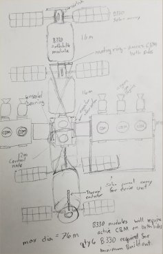
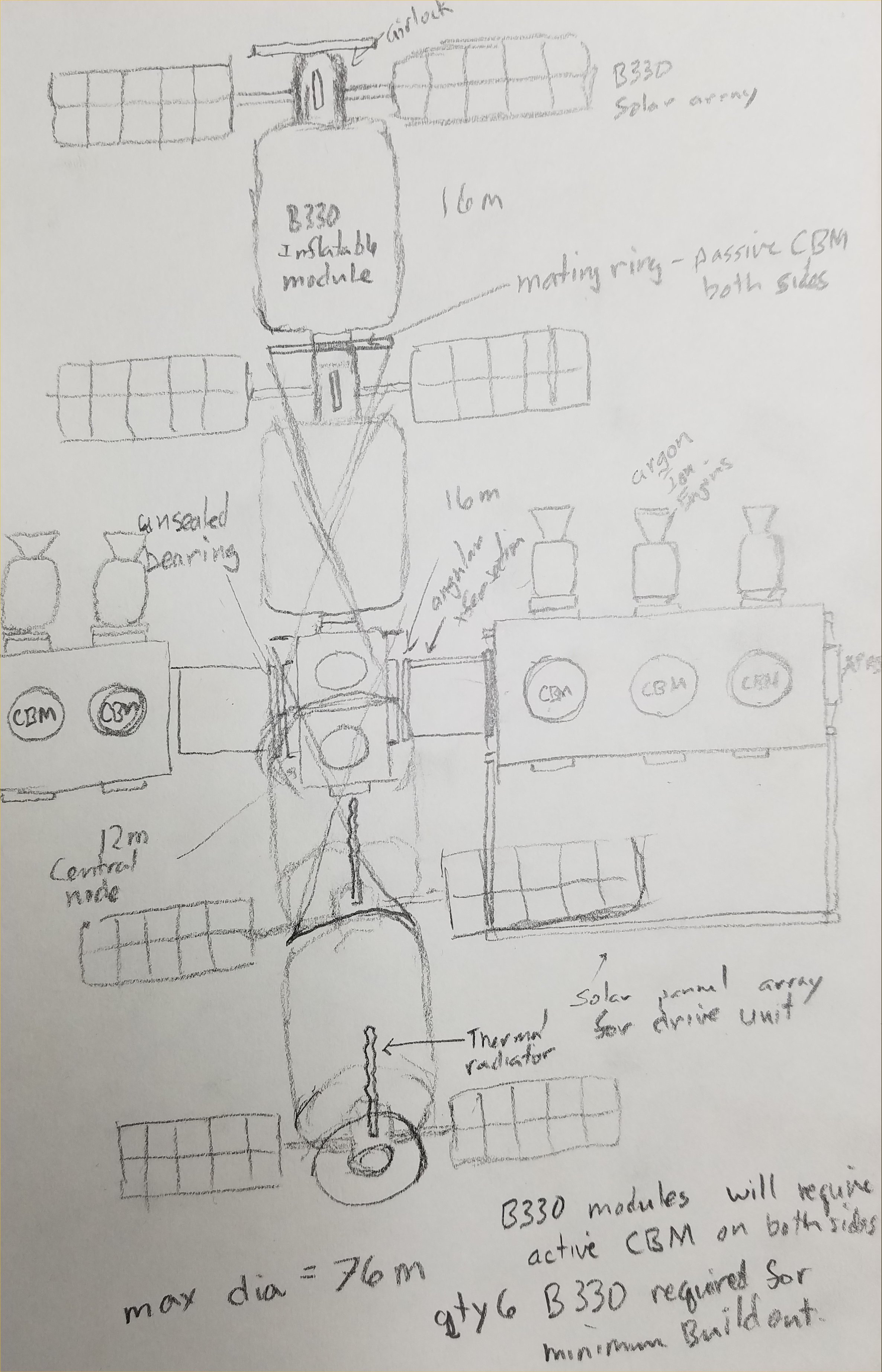
FOLDINGSS research spacecraft concept as viewed from the
ecliptic. North is on the left.
CREDIT: Glenn Clark |
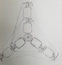
FOLDINGSS research spacecraft as viewed from the north. The
drive section is not pictured. The habitat robotic arms are
also omitted. The angular transfer device is only hinted at,
by the smaller circle shown on the central habitat hubs. In
these renderings, the habitat power unit is only shown as an
attachment point for cross bracing. Likewise the perimeter
unit is only shown as an attachment point for bracing.
CREDIT: Glenn Clark |

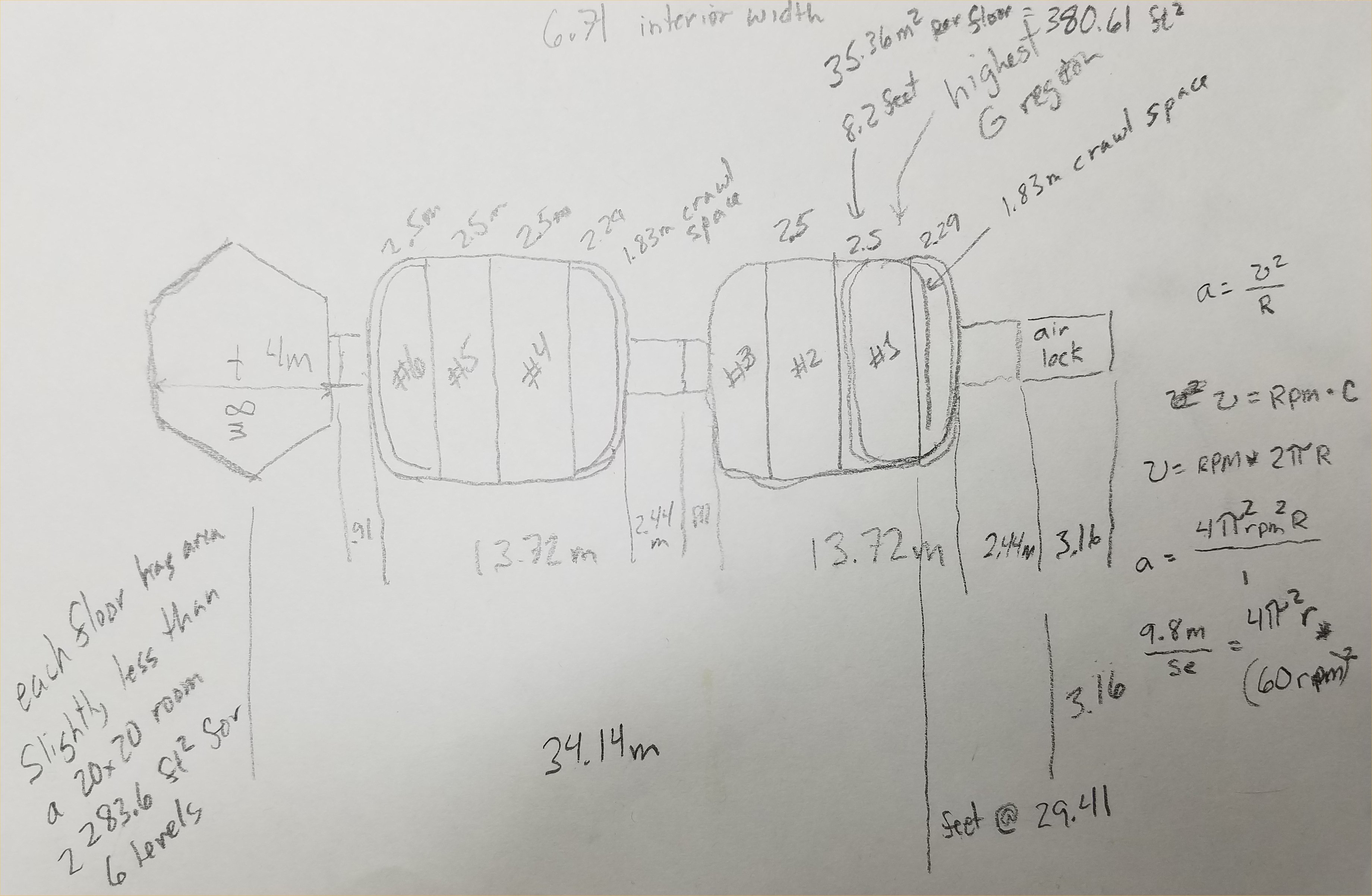
This sketch was the first concept for partitioning the Bigelow
B330 inflatable habitat envelopes into floors. The radius of
the lower floor was also significant in this sketch, as it
determines the rotation rate of the entire habitat wheel. Even
though the pressurized space inside the FOLDINGSS craft is
expansive by current spacecraft standards, it only affords
crew a shared space equivalent to a 19' x 19' room and a
private bedroom equivalent in area to a 9' by 9' room. A small
office space is afforded each crew member and 2 crew share a
galley which is also equivalent to a 9'x9' room. This is the
primary space allotted to each crew member for a 900 day
mission.
CREDIT: Glenn Clark |
|
|
|
|
|
|
|
|